Tuesday 25 October 2016

Choose your robot assembly wisely.

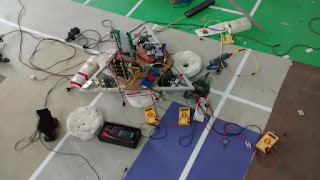
Hey, I have been working on Robocon's statement for around 9 weeks. We are trying to develop a differential drive this time. If you had followed this blog from the past then you might be familiar with the way we have developed the three-wheel omniwheel driving chassis in the Summers. In a similar fashion we started to develop the differential driving model for the robot. The driving and the output of the robot was observed earlier this week and we were successful in developing an autonomous robot using line feedback. But the estimated linear velocity for the robot was lesser than expected. To increase the linear velocity of the robot we tried to,
1. Increase wheel diameter
2. Remove gears
3. Make a gear ratio of 1:1

Last night, I tried to drive the bigger wheel chassis. We would experience some harsh noise from the motors in this configuration. Upon checking up the lower control system, the graphs revealed something that I had not taken in account.

DISCLAIMER : All the tests mentioned are free wheel, i.e. wheels in air.

The wheel showed a good critically damped transient when given a step input from rest to say 200 RPM. It would run fine (a little sluggish than the small diameter ones but okay). But upon removing the step input, i.e. from non zero high RPM to low RPM, the graph would shoot down the zero line very abruptly, almost like a spike. This resulted in change of polarity at motor terminals in very short duration resulting in the harsh noise and might even result in permanent damage of motor.

The reason for this is yet being under study but the intuitive and logical reason behind this is the HIGH MOMENT OF INERTIA of the wheel. Omniwheels had their mass almost concentrated at center thereby rendering less inertia. The current wheels have high inertia due to mass at the periphery, hence even after removing output, the wheel tends to rotate resulting in the need of a brake to stop it, generated as a negative voltage from the PID controller. So I am gonna start working on the second approach to increase linear velocity of the robot for now. This hypothesis still needs to be verified. If verified, I would like to put a statement saying, "Choose low inertia and good traction wheels."

The gist of this post was to call out to all the control workers out there that even a change in wheel (no change in robot weight, dimension, orientation, motor, actuator) can mess up a lot in the system.

- Aniket

Wednesday 22 June 2016

The derivative magic

I have been facing some problems which I was not able to solve for a few days. The problem of high rise time of the P controller and the problem of P controller over the heading control. In brief, the heading error could not be compensated using P controller for small errors because say a response of 1RPM is a very slow wheel speed. And if I gain it would oscillate till eternity.

I met a M.Tech senior (because he was facing some problem in MATLAB) yesterday and he showed me a PID video of MIT. So when I sat today in lab I thought to tinker with my controller instead of parameters or logic or frequencies. I added a derivative term and this how my system evolved,

P = 0.02, D = 0.0 This was my earlier P response. Efficient but slow.

P = 0.08
System oscillations apparently visible
P = 0.08, D = 0.1
Derivative starts nullifying oscillations
P = 0.08, D = 0.2
P = 0.08, D = 0.3
P = 0.08, D = 0.4
Almost no oscillations
P = 0.08, D = 0.5
P = 0.08, D = 0.6
Oscillations start to increase back. Guess this is D limit
P = 0.06, D = 0.5
Decreasing P gain now to damp the overshoot
Almost perfect
P = 0.06, D = 0.4
Derivative decreased a little more because it would bring some over response when motor stopped

This is the video of the robot with all wheels tuned with PD controller and the heading feedback going through a PD controller. The Heading PD controller needs further tuning.

So this was the evolution of my P controller to PD controller.

- Aniket

Friday 17 June 2016

Adding the heading control P controller to the upper control system

In the control system applied on RPi3 (upper control loop) which sends the set variable to the Tiva boards, a P regulator was implemented to keep the heading constant on the basis of readings of the IMU. The conclusions after the tuning can be seen in the video. There is a bit of drift in the heading even though.

Next step would be to give it a finesse touch and add positioning encoders to have x and y coordinate feedbacl. The loaded hysteresis curve will also need to be looked at,

Driving with control systems.

After three to four days of gathering information and plots about the dependencies and affects of various factors like PWM frequency, control loop frequency, QEI frequency etc. P cotrollers were added to every motor and tuned today. Once they gave smooth response on off load we started testing them on load.

The videos of the on load tests can be viewed below.


Today, I also worked with the Raspberry Pi 3 and solved some of the problems that took an hour to search around on the Internet. Jump to my next blogpost . We will be adding a heading feedback and PI loop to this system now.
Stay tuned!

Tuesday 14 June 2016

Junkyard science


If you haven't checked out the repository for the updates of the experiments we have been performing on the three wheel robot modules, check now.  We have compared plots on RPM vs PWM at different QEI frequency, The RPM calculation module seems to work fine till now. We have also updated the results of "affect of PWM frequency on RPM vs PWM" and found out that higher frequency gives a more linear plot but also results in heating on motor (inductance is a bitch).

So the next step is to start testing motors on load and no load behaviors and plot RPM vs other parameters. This will serve as a pre-experiment for hysteresis test. The main problem was to load the motor. Mechanical it would require the motor to have contact with some surface hence my system could not be at rest at one position (You cannot ask me to run around with my laptop, taking readings). So we took a 200RPM Vega motor, a coupler and some wires and a potentiometer. The coupler could fix perfectly to the wheel with the help of Allen bolt but the other end had quite bigger diameter than Vega's shaft. So we took suggestions from the mechanical team and tried to tie a grip around it and push the shaft firmly. But it did not work really well, so we kept trying various alternatives. Finally we pushed in some padding and drilled a hole through which another Allen bolt fixed Vega's shaft. We have added a  "Load breadboard" which has a potentiometer and it was varied such that multiples of 300mA current (max load current) flows through generator. (300mA was seen from datasheet. Used a little bit of Electrical Machines from second year syllabus to calculate values).

This is the setup.


The observations were noted on the spreadsheet and torque was calculated and found out the plots. The N vs I_armature plot was quite satisfactory and linear with positive slope and it was similar to other plots shown on the internet. But the N vs T and T vs I_armature graphs showed big difference. The graph was like an efficiency graph (inverted V type). While online sources declared it linear with constant slope. I consulted my friend about this and had some thought about it, the theory behind PMDC (as far as we know) would give us such an inverted V curve only, later I found that at many of  the graphs online it said at the end point of torque line as "stall torque" i.e. max torque. Maybe I drove my machine further more than stall torque and it resulted in this. I suppose this made the indifference otherwise the graph is quite linear before stall torque.

Please share with me your views on this whether I had done something wrong while taking readings or calculations or if it is possible etc.

So we are gonna try studying hysteresis from today. You can look for the experiment below.


Link to GitHub Repo : https://github.com/DRISHTI-SVNIT/Three-Wheel-Omnidrive-Module-Tests

Saturday 11 June 2016

Taking a better way off course.

I recently found out that my QEI (Quadrature Encoder Interface) codes were not correct. How can your brain help you stop from being hit by a street lamp if you are seeing it at the wrong place from its original place? Savvy? So we followed an advice from our mentor and sketched a module tree of our system and picked out the lower most branch of the module and start perfecting each module in the reverse hierarchy of their appearance. The scribbled rough diagram looks like this, I will try to fair it out ASAP and have my readers a look to it


I tried to vary frequency of QEI and looked if there is any redundancy in the readings and the fluctuations in the readings. While redundancy was not an issue, at 40Hz of QEI the readings fluctuated a lot. As the frequency was decreased the readings started to smoothen. This was observed and plotted on MATLAB and attached to the experiment's excel sheet which can be found here.

The next phase of the RPM calculator module will be proceeded with, tomorrow. Till then, ciao.

- Aniket

Thursday 9 June 2016

Three wheel driving - without control system

From my previous post, you can find a pdf regarding a "n wheeled driving equations". From the paper I was able to formulate equations for a three wheel drive and it followed as below,

v1 = -vx/2 + vy*sqrt(3)/2 + R*w
v2 = -vx/2 - vy*sqrt(3)/2 + R*w
v3 = vx + R*w

where,
v1 , v2, v3 are RPMs of the three wheels
vx is velocity of robot in x direction, vy is velocity of robot in y direction, w is angular velocity, R is radius of wheel

So I coded an interface for PS2 and motor control on ATMega128 controller and started testing a no control system run of the system. The code can be found here.
Considerations of no angular velocity was taken and hence w = 0. vx and vy were equalled 100cm/s initially but the response at this RPM was sluggish and often the mechanical errors dominated a lot leading to stoppage of wheels due to gear friction itself. Later the vx and vy were updated to 200cm/s and it got rid of gear friction and mechanical imperfections. Several runs were made on robot and the PWM on each wheel was "biased" according to the compensation required. For example, if the robot moved more to the left then the left wheel PWM was decreased. After testing several sets, today the driving concluded with the below results of no control system three wheel driving.

Obviously, the response is really bad. But it could be finer with some more tuning. This clearly declares the need of a control system.

Mechanical difficulties faced :

  • The L mountings of the motor has very less ground clearance and hence touches unlevelled ground.
  • Positioning wheels Allen bolts might have threads worn out.
  • Gear friction is considerable.
  • Some eccentricity on gear mountings.

Wednesday 8 June 2016

Getting started with Three wheel omnidrive driving

So I will put up from where I left last time. I was working on four wheel omnidrive robot till my teammates worked on fabricating the three wheel chassis. Finally it was completed last week and we have started shifting the driving from four wheel to three wheel.

Probably, shifting the electronics and control system might only round up to changing the equations that correlate the individual RPMs and linear and angular velocity of robot. I found a really good paper work on it which can be found here.

Today we completed rewiring the triwheel chassis and managed to test all motors. Successfully tuned two of the motors but couldn't tune the third due to mechanical malfunctioning observed in it. The following are the videos of the P-regulator responses by each wheel, Used Tiva TM4C123 Launchpad. Due to lack of resources, we could accomplish only this much today.


The next steps will probably be to arrange the resources as soon as possible and make the changes in the equation and start trying out a no heading feedback system ASAP to compare triwheel and four wheel and solve actuator problems.

Thursday 12 May 2016

Four wheeled omnidrive robot driving

It has been quite a while since I last blogged. I have been working on driving of a mobile robot lately. Driving plays a really important role in case of a mobile robot. So what do I mean by driving?

Driving is basically another term of control of mobile robot. Controlling a robot's motion ain't as easy as you think at the first approach. The first robot you ever made might have had four motors with two switches controlling motor state on or off. If you had been a genius then you might have had even applied some embedded electronics and microcontrollers to make a variable speed robot using PWM. The systems mentioned above were open loop systems.

Open Loop v/s Closed Loop
To understand importance of driving, consider an example where you are walking on the side of a road. Now if you were an open loop system, you must have been blindfolded. Maybe you could have a person giving you inputs of where to walk. But would you risk your life by walking on the road blindfolded on someone else's input?

Here's the drill, the input and feedback are the important terms here. A system with no feedback but only input signals can be called open loop while a system with feedback is, of course, a closed loop.

The advantages of a closed loop system is that the system knows what output it gives out and gets feedback from outside world what output actually reached in the world. Here comes the concept of error. Error is, as usual, the quantity you desire minus the quantity you have currently. In closed loop systems, this error is the subtraction of feedback signal from input signal. This error is fed in an error reduction algorithm or controllers that change the output according to the error. The famous PID controller is one such controller. Google about it.

Why Driving?
So let's get back to where we started. Why driving? Because running four motors (in my case 4) at the same time irrespective of load ain't a piece of cake. And for a "perpetual mechanically perfect" robot, it is a must for all the motors to run at the same rpm in order to get a nice straight resultant direction of motion. Autonomous robots have these skills as their prerequisites. Plus driving ensures the robot to be immune of the external forces disrupting its path, for e.g. if you increase load on one wheel, then by nature, the rpm of that wheel should be decrease. This decrease in rpm can be fed back to the system which then will compensate the rpm of this wheel to make it back normal and hence the resultant direction shall be unchanged. (Theoretically)

Driving of robots can also be further expanded to line tracing, curve tracing, swarm robotics etc.

Currently I am working on Texas Instruments Tiva C series microcontrollers and Raspberry Pi 2 to apply my CONTROL SYSTEM on the robot. Control system. Explore it. Driving is an application of the control theory.

Aniket.